2 Controllers with Munro Smart Pump Relays. Does it work? Yes / No? - Troubleshooting / Sprinklers & Irrigation - Rachio Community
Home | Support | Status Page
2 Controllers with Munro Smart Pump Relays. Does it work? Yes / No?
Troubleshooting Sprinklers & Irrigation
You have selected 0 posts.
4.5k views 16 likes 3 links
28](https://community.rachio.com/u/AngryIrrigationMan "AngryIrrigationMan")
15](https://community.rachio.com/u/Gene "Gene")
6](https://community.rachio.com/u/DLane "DLane")
4](https://community.rachio.com/u/franz "franz")
read 12 min
Top replies
2 / 54
Aug 2019
post by AngryIrrigationMan on Aug 1, 2019
1
I can’t seem to find a definate answer to the following questions - and wanted to see if I can get Yes/No answers - and any other suggestions regarding the Munro Smart Pump relay that allows 2 controllers to control a single pump/source. The Smart Pump performs other great features to save your pump too but I don’t want to get off track here.
Yes or No: Does Gen 2 or Gen 3 controllers work with Munro Smart Pump Relays without showing zone fault errors? (ie two controllers connected the Munro smart relay)
Yes or No: Has Rachio product / support / dev actually tested with the Munro Smart Pump Relays?
Yes or No: Has anyone fixed / found a work around for Zone Fault messages when two controllers are connected to the Munro Smart Relay Pump?
\\\* Background ****
I have been going through this effort for the past 3 years performing a lot of troublshooting:: measing voltage drop, rewiring all wirded connections, running new master value lines, working with Munro support/replacing their relay/testing their circuits, etc – Even thought all this effort - it seems that the Rachio controllers still somehow indicating a ‘Zone fault detected / master value may have wiring issues’. I am 99.99999 % sure at this point all my wiring is top notch / done correctly.
Bottom line: I think the 2 Rachio controllers are getting ‘confused’ by seeing each other being connected to the Munro Smart Relay (controlling the power to the pump, etc) - and causing the fault error. Is that possible?
What is happening I have 1 16-zone gen3 controller and 1 8-zone gen 3 controller connected to the Munro Smart Pump relay - with all heavy gauge wire and are all with acceptable voltage drop for the controllers and relay to operate (already been that path with Rachio’s great support teams and Muro’s senior engineer that personally look interested in helping me troubleshoot this). What is happening is that I get RANDOM zone fault messages - stopping the scheduled job or a manual job. It is completely random - as I have tried 1000’s of variations over these 3 years to isolate the problem - rewiring everything, trying different sequences of zone, turning on controllers in different orders, putting time pauses between running zones, making sure jobs are not trying to run at the same time, new replacement solenoids, etc…
I also say that because when this fault occurs – and it’s a lot: once every 3 or 4 cycles at least, if I simply keep restarting the job a couple of times from the app or manually from the controller, it eventually will works – but that usually takes 2 ot 3 faults first – but it will eventually work.
\\\* My Thoughts about a Solution ***
Through all of this – the error seems to boils down to if when BOTH controllers are connected to the relay, it produces these random fault messages. If only one controller is connected to the smart pump relay - and the other controller is physically disconnected from the Smart Pump Relay, then one connected controller works just fine never generating a fault. In my troublshotting, I have even alternated controllers - same results. I have even the upgraded both controllers from gen 2 to gen 3, tried the combination of these, etc… That was a pricey way to troublshoot - but same results. Bottom line – when both are connected – that’s when the fault errors are triggered.
Additional Considerations: Like I mentioned, I had the issues starting with my Gen 2 controlers - but when I moved to the Gen 3 controllers, I get A LOT more over these fault errors. Leading me to believe it’s something in their SOFTWARE reacting to a voltage/amperage issue triggering this message / shutdown when two controllers are connected to the smart relay. My theory is that controller 1 sees controller 2 over the relay – and that is causing the master fault error condition - and they lowered that threshold for the fault.
My gut is telling me there should be another system flag that Rachio needs to set / trap to deal with two controllers being attached to the Munro Smart Relay. I could be wrong on this – but I am reaching out because there doesn’t seem to be clear answers to questions on using 2 Controllers with the Munro Smart Pump Relay. Perhaps I am missing a setting somewhere (please tell me that is the case!)T
Thus my questions:
Yes or No: Does Gen 2 or Gen 3 work with Munro Smart Pump Relays without showing fault errors?
Yes or No: Has Rachio product / support / dev teams actually tested 2 controllers with the Munro Smart Pump Relays? (again two controllers connected the smart relay)
Yes or No: Has anyone fixed / found a work around for Zone Fault messages when two controllers are connected to the Munro Smart Relay Pump? (are they seeing each other and that could be causing the fault condition to trip)
Thanks for your thoughts and suggestions!
4.5k views 16 likes 3 links
28](https://community.rachio.com/u/AngryIrrigationMan "AngryIrrigationMan")
15](https://community.rachio.com/u/Gene "Gene")
6](https://community.rachio.com/u/DLane "DLane")
4](https://community.rachio.com/u/franz "franz")
read 12 min
Top replies
post by DLane on Aug 1, 2019
@AngryIrrigationMan - which model of the Munro Smart Pump relay is being used? The reason I ask is in a prior post it was noted there is a lower power drawn Munro model that did work. See →
I’d also consider isolating the controllers from each other using a SPDT relay (approximately $7 on Amazon) as was diagramed/discussed in this post →
If it is truly a current draw issue with the Munro device, then one could use two NO (normally open) SPST (single pole single throw) relays wired in parallel with each relay coil controlled by a different Rachio M terminal. The power from an external power supply (2 Amp +) would go through the Common/pole terminal on the relays with the NO term connected to the Munro pump start signal and the common/return from the Munro back to the external power supply.
So while I don’t work for Rachio, here are the answers to the three questions.
I believe so with a low power draw version as mentioned in earlier in this post.
I doubt it as I would think this would be a rare case for them to spend the time/trouble/effort to test.
See the above solution to isolate the controllers from each other, with or without a beefier external power supply.
post by AngryIrrigationMan on Aug 5, 2019
@DLane A hearty thank you for your detailed reply! Your level of detail was the life-raft and sanity check that I needed - and at the same time made my head hurt! Also thank you for including the other threads as the diagrams were very helpful.
Bottomline: I think you hit the nail on the head - I am using a 220V pump.
With that in mind, I was wonder if you can expand on your reply as you stated the following as a possible way forward:
“If it is truly a current draw issue with the Munro device, then one could use two NO (normally open) SPST (single pole single throw) relays wired in parallel with each relay coil controlled by a different Rachio M terminal. The power from an external power supply (2 Amp +) would go through the Common/pole terminal on the relays with the NO term connected to the Munro pump start signal and the common/return from the Munro back to the external power supply.”
I have two questions:
First - is this the correct NO SPST:
https://www.amazon.com/URBEST-HH52P-Electromagnetic-Power-DYF08A/dp/B00NN5ABG2/ref=pd_cart_vw_crc_1_3/132-3164648-6791922?_encoding=UTF8&pd_rd_i=B00NN5ABG2&pd_rd_r=a6dedbcd-667a-48e5-8257-41a8e73ec429&pd_rd_w=oTDOV&pd_rd_wg=U6iv8&pf_rd_p=7b1a11cb-b9d6-4645-a52e-34c86ca37029&pf_rd_r=N4ZWA8XMJRE28N7WRQPG&psc=1&refRID=N4ZWA8XMJRE28N7WRQPG In case that link doesn’t work, it’s the “URBEST HH52P AC 24V Coil DPDT 8 Pins Electromagnetic Power Relay w DYF08A Base” from Amazon
Second - can you expand more on your quote as I get lost at the second sentence – starting with ‘The power from an external power…’ I think I have it – but I just hate letting the smoke out of these things
post by DLane on Aug 6, 2019
@AngryIrrigationMan - you’re welcome! The current draw isn’t related to the current or voltage (a 220v pump will pull about half the amps a 120 volt pump will for the same size) the pump draws, but rather the current the pump start relay needs to close the relay and energize the pump.
Here is a Visio drawing I quickly hacked together.
\ image.png644×654 5.74 KB](https://community.rachio.com/uploads/db1097/original/2X/6/6886e5079fb1d2f2c87e9f31dce2a32a3310e6ac.png "image.png")
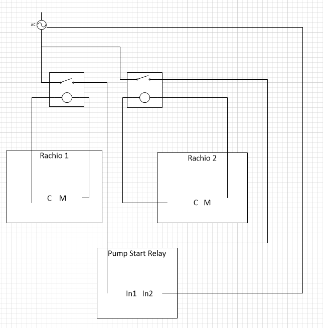
That relay will work. I prefer a sealed unit like ->
Let me know if you have any other questions.
Again - YMMV.
post by franz on Aug 6, 2019
franz Co-Founder/CTO @ Rachio
post by AngryIrrigationMan on Aug 13, 2019
DLane](https://community.rachio.com/t/2-controllers-with-munro-smart-pump-relays-does-it-work-yes-no/20585 "Load parent post")
Many thanks as that was definitely helpful! So I ordered these relays and they arrived - just in time for me to have to head out a couple of weeks (sigh…).
I will work on that when I return but in the meantime, I do have a question: I am not familiar with relays enough to translate your Visio diagram into the actual 6 pin layout of the physical relay. I have been trying to do my homework on this and I found the following information about the relay but I can’t verify it is correct. “Pin pair 2 & 4 are normally closed; Pin pair 2 & 5 are normally open. Pins 1 & 3 are the 24V coil contacts.” Assuming this information is correct, based on your directions, my power source for each relay would run across pins 2 and 5, and then Rachio C/M across the 2 and 4 pins. Forgive me for not having the exact lingo down as I generally resort to simply getting a bigger hammer. But do I have that correct?
I have a feeling this sense of security I have at this moment will disappear when I open the box and start tracing wires in a couple of weeks but I look forward to that challenge! (gulp)
post by DLane on Aug 14, 2019
@AngryIrrigationMan - close. Here are the wiring connections:
Rachio C to Relay 1
Rachio M to Relay 3
Power supply lead to Relay 2
Lead from relay to pump start relay to Relay 5
and then the other side of the pump start relay trigger line back to the other line on the power supply.
There should be numbers by the pins on the relay (I think). If not number then NC - normally closed (pin 4), C - common (pin 2), NO - normally open (pin 5) and the other two would be for the coil. Also a ohm meter can be used to identify pins if necessary.
You’ve got this. Safe travels and have fun. We’ll be here if there are any questions when you get back.
Please post the results (success!) when it is installed and working.
1 month later
post by AngryIrrigationMan on Sep 24, 2019
Ok - after some delays, I am finally back in action and about ready to tackle this. Two things - here is the schematic for the Munro system: Is there anything on this that would indicate a different wiring setup?
\ munrowiring-property214.jpg1267×1175 584 KB](https://community.rachio.com/uploads/db1097/original/2X/f/f064f1b65fbd85eef870aa33c50a920a71542cb0.jpeg "munrowiring-property214.jpg")
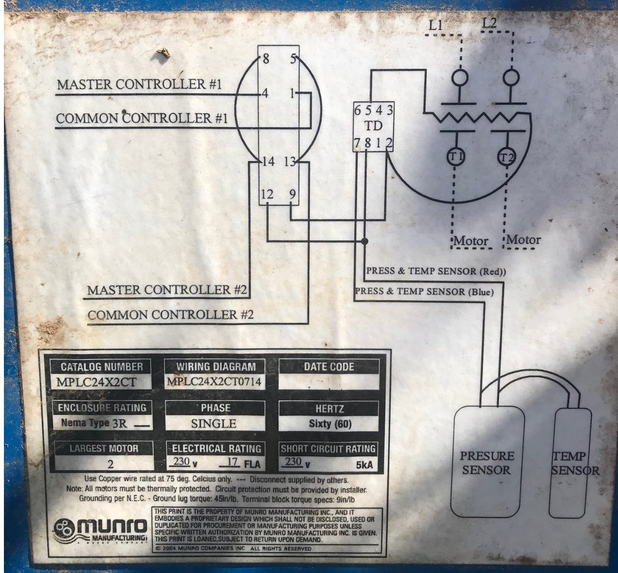
I have started to pre-wire and label as much as I can. Here is the basic rig setup (just relays on a board):
\ relaysforprop214.jpg1331×1115 512 KB](https://community.rachio.com/uploads/db1097/original/2X/b/bda7262c7a36fa05d3121e4cde7f39115c7b2502.jpeg "relaysforprop214.jpg")
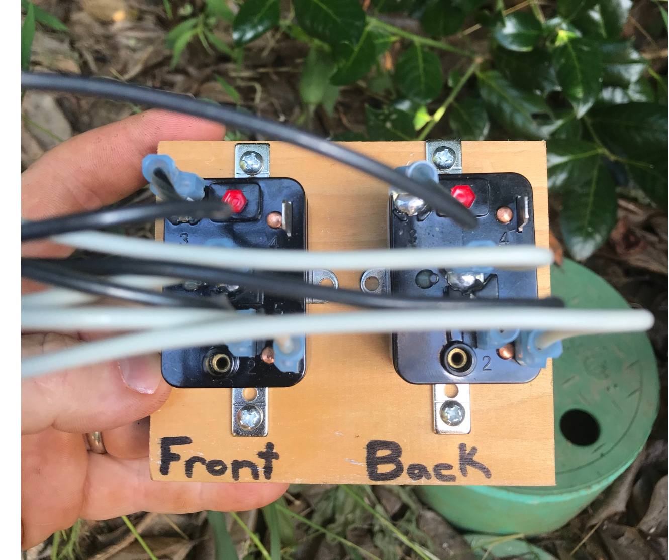
post by AngryIrrigationMan on Sep 24, 2019
1
Last but not least, here is the actual current setup - where the rubber meets the road:
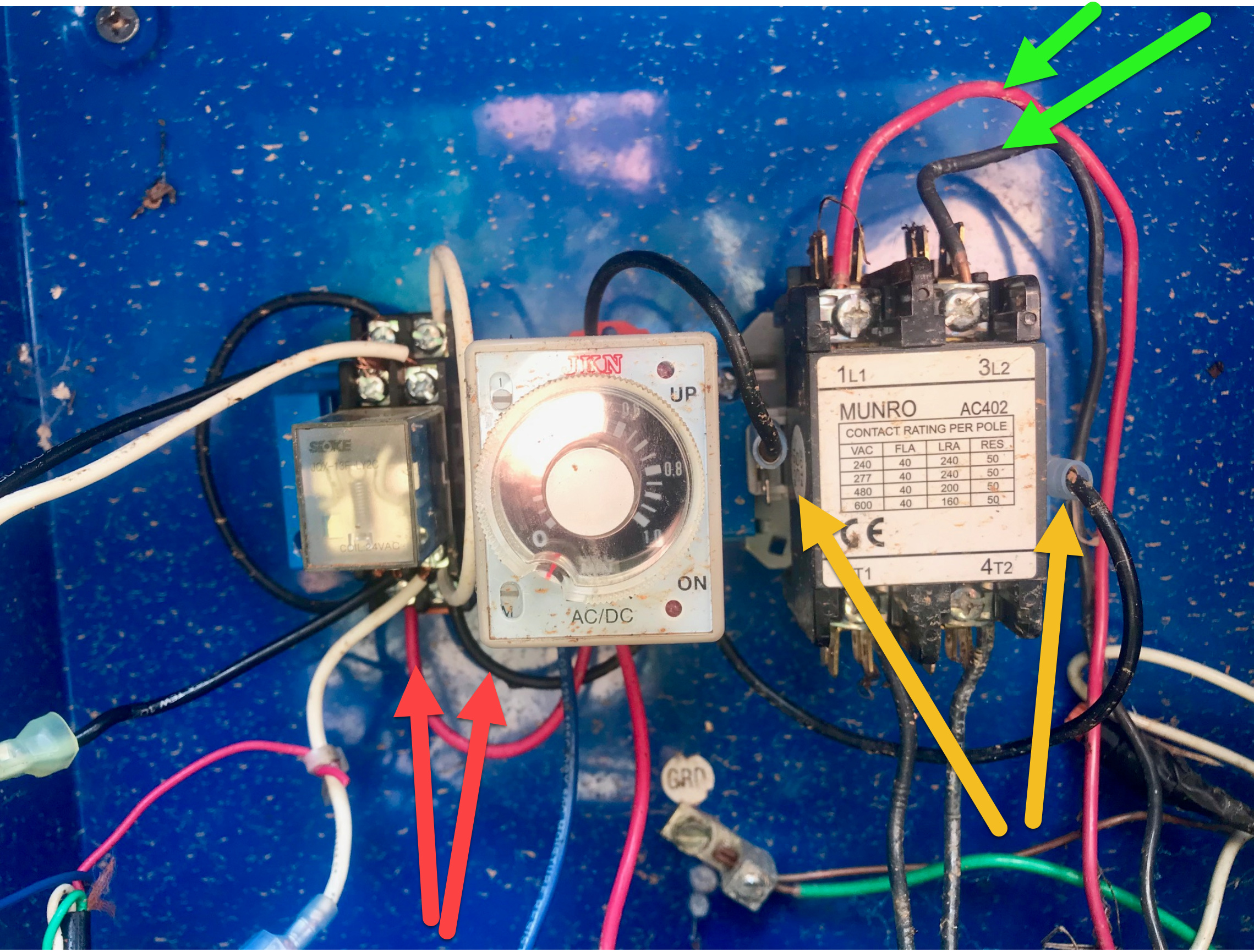
\ munroboxdetail.jpg2016×1512 696 KB](https://community.rachio.com/uploads/db1097/original/2X/7/79552be10c8a9fd47eb4fa4db05770f2382c5c95.jpeg "munroboxdetail.jpg")
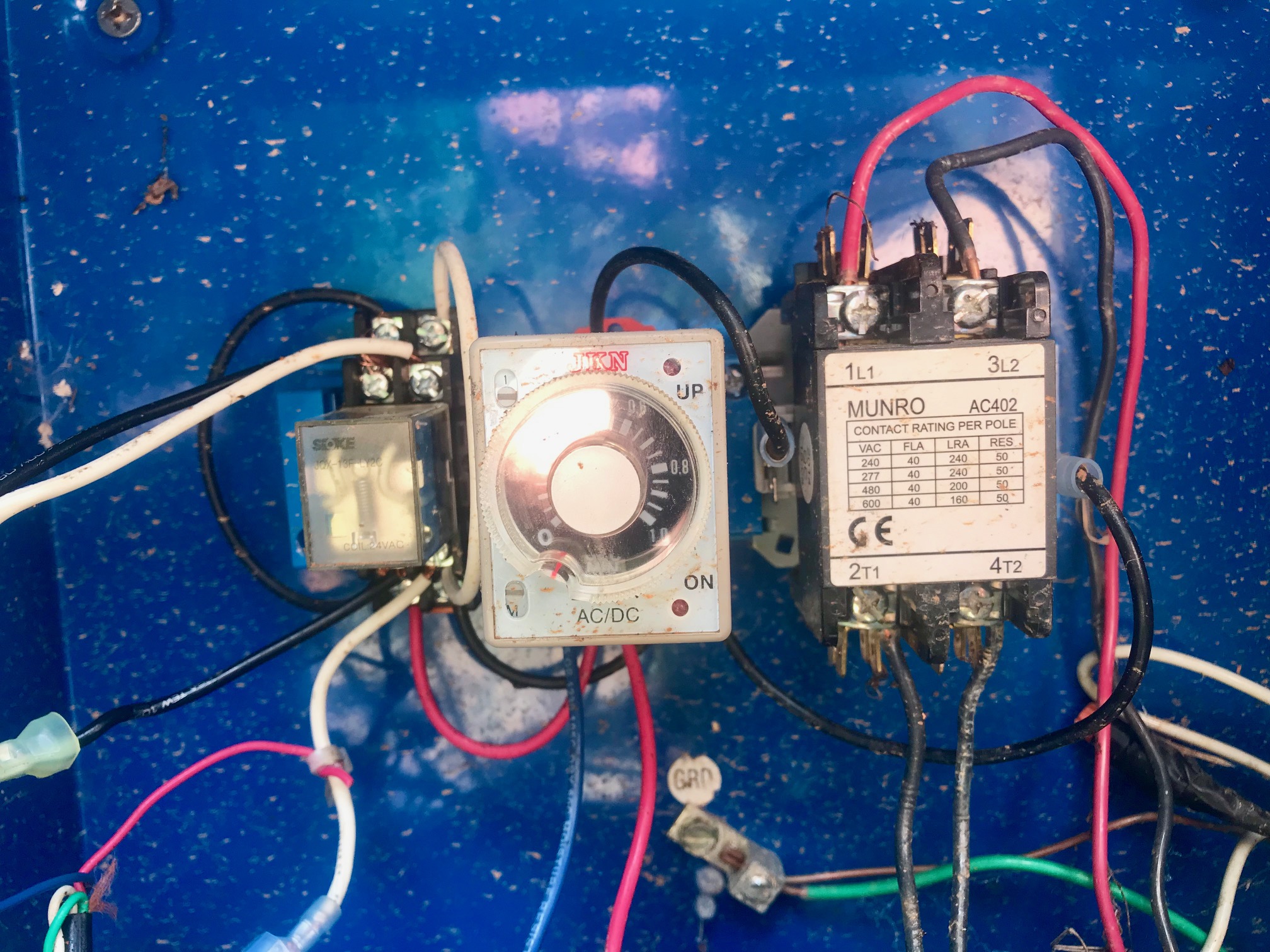
My question is - how do I weave in the pressure and tempature switch here? My gut is telling me I have to do something with the wires with the RED arrows here:
\ question-doublecheckpowersourcefeed.jpg2279×1731 1.34 MB](https://community.rachio.com/uploads/db1097/original/2X/a/a5627f7760ac2155ca66f6b5f672533d4dfb6c10.jpeg "question-doublecheckpowersourcefeed.jpg")
post by DLane on Sep 25, 2019
@AngryIrrigationMan - sorry for the delay in responding, been traveling and busy.
I believe the correct connections are on the relay to the left of the JKN time delay device. The connections are listed as 1, 4, 13 and 14 on the wiring diagram. Check to see where the wires for the top two terminals on each side go. I’m guessing they go back to the current controllers.
It looks like one can wire the Front relay to 1 and the back relay to 14 with the common return to the separate power supply to 4 and 13 and not have to join the output from the relays together. Or one can join the wires together and just use terminals 1 and 4.
@Gene, did I Bozo anything here?
post by AngryIrrigationMan on Sep 25, 2019
Thanks for the initial insights on that on the pressure/temp switches - and while that is brewing, let me give you a status update: So I wired everything in but I couldn’t get the pump to turn on. I could hear the relays activate when I turned on each controller but the pump wouldn’t turn on. I didn’t have time to see if I had any voltage out of Relay pin 5 - as I was running out of daylight and I realized they just seeded/couldn’t miss a cycle tonight. So I disconnected my rig and reconnected the old setup to get through the night (worked just fine then). I’ll try again tomorrow as I’ll have more time to troubleshoot (make sure I double check all my connections correct, etc…).
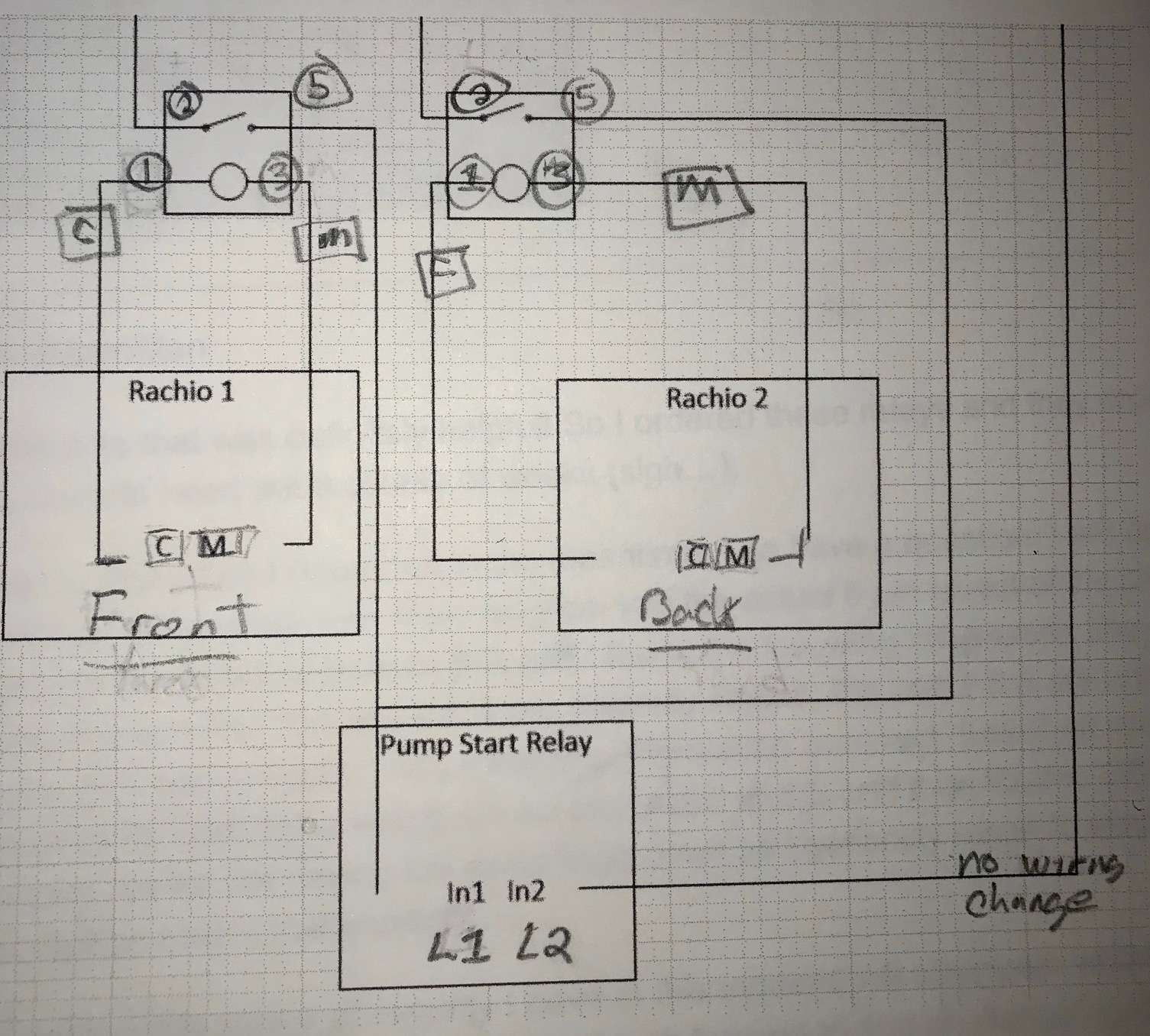
By the way, I marked up your Visio driagram with the following to make sure I have things correct:
\ wiringwithrelaypins.jpg1505×1356 572 KB](https://community.rachio.com/uploads/db1097/original/2X/5/5325aa5a13b675dabe7531b5164270c1117195c7.jpeg "wiringwithrelaypins.jpg")
post by Gene on Sep 26, 2019
1
@AngryIrrigationMan your drawing looks good, but you should be using terminal 4 instead of 5 on the Supco relays. Terminal 4 is your “input”, 2 is Normally Open (NO) “output”, 5 is Normally Closed (NC) “output”. You are driving them correctly with terminals 1 and 3, thus you can hear the relay click.
@DLane Got lost in the wiring diagram, would have to investigate what every relay actually is on the old timer/temperature board in order to provide any feedback. What you’ve wrote seems good, lets try it and see
post by AngryIrrigationMan on Sep 26, 2019
Update: I switched to terminal 4 from terminal 5 - no luck as the pump will not turn on. With my volt meter, I do have voltage going to the Pump Start Relay from terminal 4 when a controller is turned on - but the pump doesn’t turn on. Does this mean I have the wrong relays that may not be passing enough amps/volts through them?
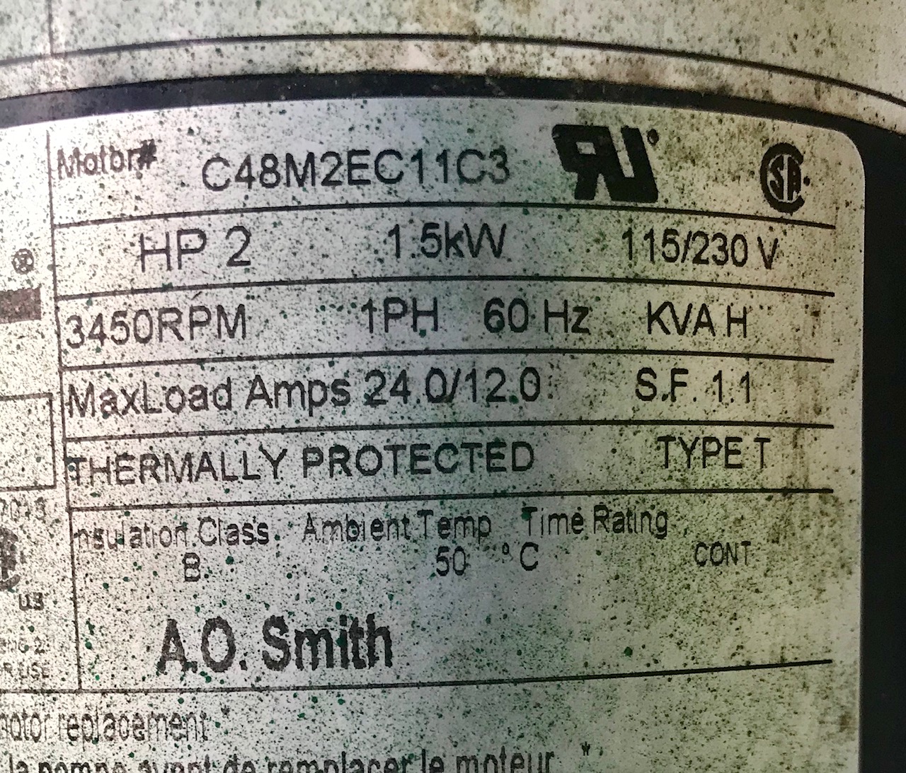
Here are the specs of the pump:
\ pumpspecsforprop214.jpg1280×1093 582 KB](https://community.rachio.com/uploads/db1097/original/2X/b/ba7536389088eb40472d82801327cd66df7a5b14.jpeg "pumpspecsforprop214.jpg")
post by AngryIrrigationMan on Sep 26, 2019
FYSA: I need to retest everying in the morning. When I was testing the new relay rig today, I disconnected the YELLOW arrows above (the connections from the Pump Relay to the JKN timer) to make sure that wasn’t causing any issues with the new relays. BUT what I just discovered was that old setup also does NOT work with those disconnected. So I will reconnect those with the new relay rig setup tomorrow - and I’ll keep eveyone posted.
post by DLane on Sep 26, 2019
@AngryIrrigationMan - I’m betting that when the wires are connected back form the JKN timer to the pump relay it will work. If there is current (24 VAC???) on those wires I think that is what causes the relay to close. If the wires are still disconnected and the Rachio is run is there a voltage potential between those two wires?
I believe the JKN device keeps the pump from rapidly restarting (i.e power outage, multiple units, etc.) and integrates the pressure and temperature switches. If everything is ok, then it provides power to the relay unit.
Thanks for the update. I think you’re very, very close.
@Gene - lost?? Tell me it isn’t so. Also, great catch on the relay terminals!
post by Gene on Sep 27, 2019
@DLane, lets just say that schematic shown on the cover of the Munro box has raised more questions than it has answered I’m actually away in Europe as well, didn’t want to go down that rabbit hole just yet
post by AngryIrrigationMan on Sep 27, 2019
Update: I tried the relay rig with the wires to the timer connected - no luck. Same results as before: hearing the relays turn on/off - and voltage out of terminal 4: but the pump doesn’t turn on. I’ll try to shoot a video of my wiring to see if something catches your eye.
post by AngryIrrigationMan on Sep 27, 2019
FYI - I shot a movie but it’s too large for me to post but I don’t think it shows anything noteworthy.
post by Gene on Sep 27, 2019
AngryIrrigationMan](https://community.rachio.com/t/2-controllers-with-munro-smart-pump-relays-does-it-work-yes-no/20585 "Load parent post")
OK, after another look at the smart box that you have, I see that the relay on the left has the same pinout as those I usually recommend, that makes understanding everything easier.
The problem is that your old setup already has provision for a 24V input to drive internal output and run the pump. Currently that input is left unused, thus the Munro smart box does not let your pump to turn on.
\ Slide1.JPG960×720 188 KB](https://community.rachio.com/uploads/db1097/original/2X/8/8a61d3b899e310bc8f5f396e8a39c28d8c5127c1.jpeg "Slide1.JPG")
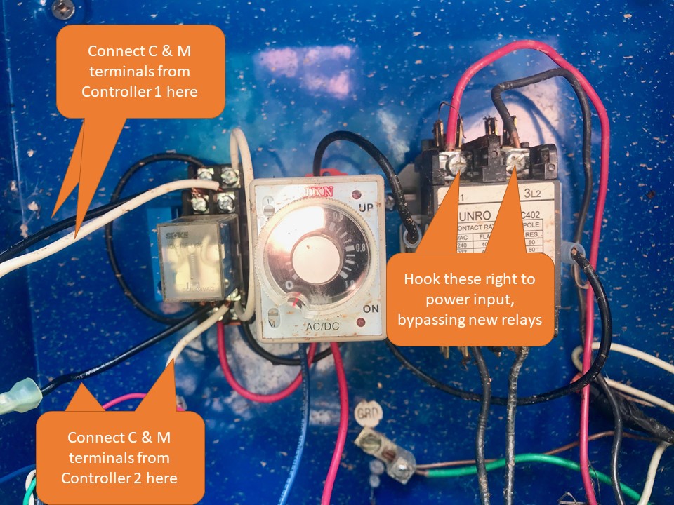
Solution is to try hooking everything up through the original instructions on the cover. You would not need to use the two new relays and instead drive the on-board inputs that come with your smart box.
post by AngryIrrigationMan on Sep 27, 2019
Hello @Gene! When I do that (use the old setup - I am very familar with that), I get the same errors from Rachio as in my original post: To summarize that: 8 out of 10 times when I turn a controller on or it runs on a schedule - it fails as I get the Rachio error messages that ‘Zone fault detected on controller X’. I have changed/checked all solioids, I ran thicker guage wire to ensure sufficient voltage from the controllers to the Munro box, etc… Also if I disconnect either controller, it works just fine with no wiring fault errors, etc… At first I thought it was a software item - but you can see that all above.
post by Gene on Sep 27, 2019
Sorry, I am catching up on the thread from the wrong end, I fear I’ve skipped your original write-up.
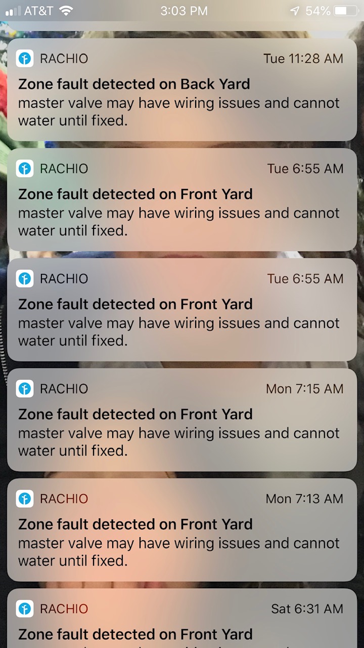
May I ask if the zone fault error you’ve described, is primarily dealing with the master valve or a random zone?
I think what you would try is connecting all of the commons from your two controllers together. Basically add a wire bridging a common terminal on one controller to the common terminal of another.
post by AngryIrrigationMan on Sep 27, 2019
No issues - and I appreciate your help while traveling!
Master value:
\ forGene2.jpg720×1280 193 KB](https://community.rachio.com/uploads/db1097/original/2X/b/b7a556b758593955274b507c0a409e893ecfa3a3.jpeg "forGene2.jpg")
post by Gene on Sep 27, 2019
1
Do you have your schedule set so that both controllers may end up running at the same time?
The issue may be that when one controller is active (#2), the second controller is completely disconnected from the load.
Try hooking up one of your new relays as a dummy load to terminals 1 and 4 of the left relay within your old munro smart box. Please note that the relay should not have any load attached, meaning that terminals 2 and 4 (or 5) of the new relay should not have anything attached on the new relay.
post by AngryIrrigationMan on Sep 28, 2019
1
There was only one scheduled item on one of the two controllers - and I know about conflicting schedules.
All these are from ‘Quick Runs’ testing the controllers. As I was saying, this happens a lot!
I am going to try both you suggestions now. I’ll keep you posted.
post by AngryIrrigationMan on Sep 28, 2019
Step 1: Creating a bridge for the commons: Using the OLD/orginal setup and the new Relay Setup I created a bridge between the two commons: no change / still get the master zone faults in the orginal setup, and just the relays activating without the pump turning on.
Step 2: Question about your instructions here:
“Try hooking up one of your new relays as a dummy load to terminals 1 and 4 of the left relay within your old munro smart box. Please note that the relay should not have any load attached, meaning that terminals 2 and 4 (or 5) of the new relay should not have anything attached on the new relay.”
My question: I am assuming that I am using the new relay rig/diagram for this test? And if so, with the left relay acting as a dummy load, should the right relay still be wired up according to the diagram or be completely disconnected? Or am I using the original Munro setup and just putting the load on the left relay as you stated?
post by Gene on Sep 28, 2019
Sorry about confusion about the dummy load, the idea is to use old (original) setup and add to it one of the relays from the alternative setup to be connected to terminals shown on the cover picture you’ve shown earlier
post by Gene on Sep 28, 2019
3
To shed some extra light on what I mean, you would be working with the relay within your smart box, particularly this one:
\ crop.jpg581×615 80.4 KB](https://community.rachio.com/uploads/db1097/original/2X/1/191ff1bc4c93ac3a2fd98f4e8dd8e6462dd47baa.jpeg "crop.jpg")
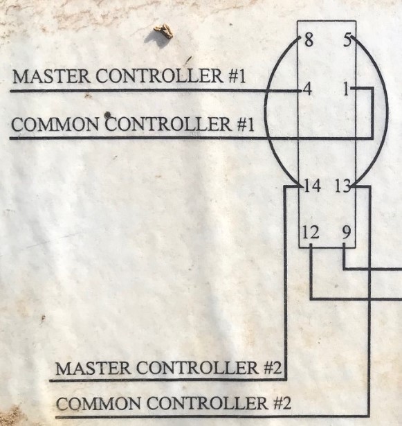
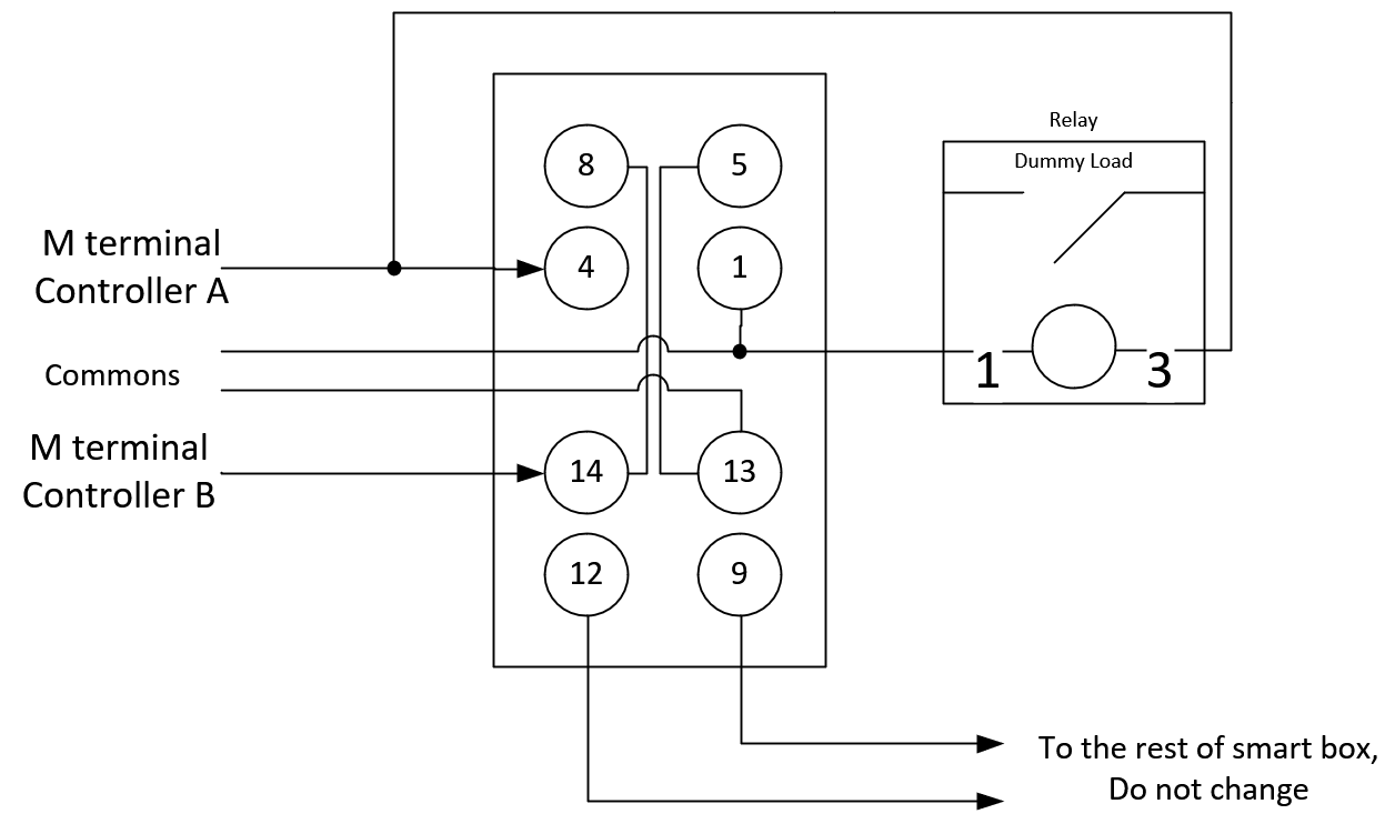
Option A would be to add the new relay you’ve bought to be in parallel with Controller #1 (A), basically terminal 4 would have two wires connected to it, connection can be made elsewhere using a wirenut or something similar.The dots on the drawing indicate wires that are connected. Connection can be done at the terminal screw or elsewhere via a wirenut.
\ Option B.PNG1256×751 19.4 KB](https://community.rachio.com/uploads/db1097/original/2X/1/1afa14c6bf200379ceb5c5457261cd9c3ffde48f.png "Option B.PNG")
Option B does not require a new relay to act as a dummy load, but does require an additional wire to run from one of the controllers (which ever is easier) wire should come from SC terminal (in case you have a Gen 2 controller) or 24V- terminal (in case you have Gen 3). This configuration is a version of a setup known to work (link)
NOTE! I’ve accidentally left the original jumper from terminal 14 to terminal 8 in place in below diagram. For this option this jumper should be removed (see the post below).
\ Option A.PNG1282×702 18.7 KB](https://community.rachio.com/uploads/db1097/original/2X/0/0d72dbd7cc2b44328a359f0b45fcc72f933d845e.png "Option A.PNG")
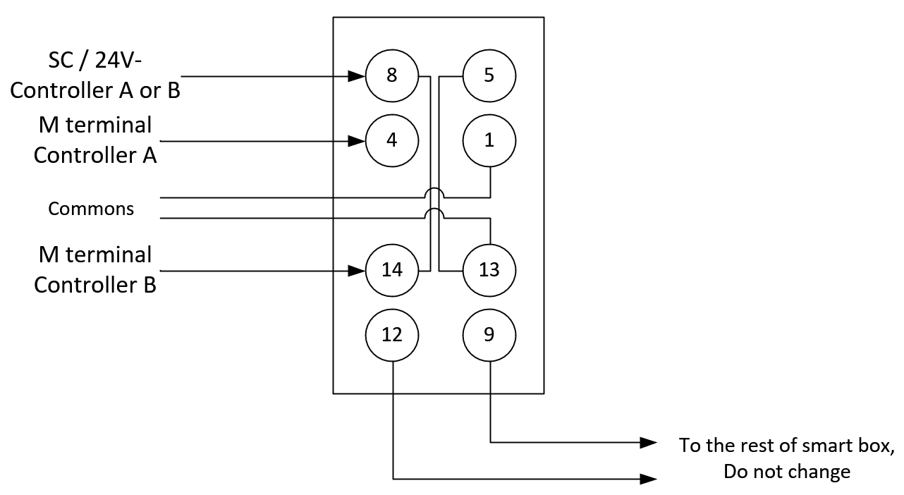
I’ve edited the drawings to minimize amount of changes. Just keep in mind that the right side of the relay (terminals 5,1,13 and 9) are all commons and can be interconnected elsewhere.
post by AngryIrrigationMan on Sep 29, 2019
Wow - thanks for all this detail! I think I will try Option A. Conceptual I think I see what’s going on but
I have 3 questions that I think somehow all tie together:
From the question about the dummy load instructions - I see you mention terminal 4 twice (to connect it and also not to connect it). Can you clarify that for me?
I have Gen 3 controllers - and I am not familiar with ‘SC’ and ‘Commons’ in the diagram. Are these just the C wires from each controller?
In your diagram - as you say ‘The dots on the drawing indicate wires that are connected’. I am not sure I see dots on my display for option A. I am not sure where the new relay should be on that diagram. I have a feeling that has to do with my first question but I can fully wrap my head around it.
post by Gene on Sep 29, 2019
2
Sorry, when posting updated drawings, I’ve mixed Option A & B diagrams. You originally observed Option B diagram for option A description and visa versa.
SC terminal is a terminal on a Gen 2 controller. Gen 3 has it labeled as 24 V - terminal.
Commons are lines connected from any available C terminal, in case you commons from two controllers tied together. (C terminal of one controller connected to C terminal of another).
Note that you can get away with just one common wire, if you move the original jumper from terminal 5 to terminal 9 and use original common hookup on terminal 13 (Labeled common controller #2).
\ 1C.PNG1287×681 18.1 KB](https://community.rachio.com/uploads/db1097/original/2X/8/81a1e1a163c4d00bf6dd4bcf8cebd859649c38ad.png "1C.PNG")
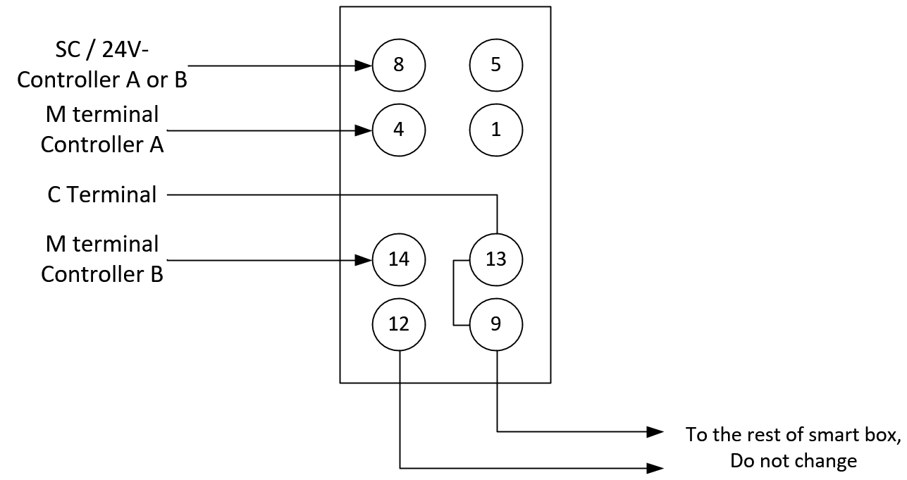
Update: Please note to remove original jumper from terminal 14 to terminal 8 with the Option B configuration. I’ve accidentally left it in during my write-up.
post by AngryIrrigationMan on Sep 29, 2019
Thank you for the clarification on the SC with Gen 2 and the common lines. I am tracking and ready to go.
To make sure I understand the correct options - I didn’t want to have to run a new wire and conduit as I did just that to increase the guage for my master value wire. While I do have a couple spare solinoid wires in my boxes/controllers, I fear the voltage drop will be too large. So what is the version that will not require me to run any extra wires for that SC/24V wire? Is that this one:
\ image.png1256×751 19.4 KB](https://community.rachio.com/uploads/db1097/original/2X/8/8c8eed7a0ed88e7e69bf633ec762108ff3bca0c5.png "image.png")
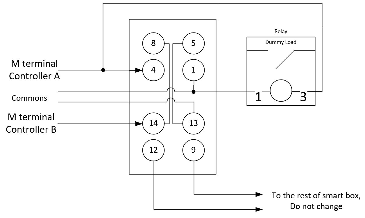
post by Gene on Sep 30, 2019
1
correct.
By the way. Power required via 24V- terminal is at most equal to a regular zone line. In case you have a spare zone wire available, do use that, it will be more that enough.
post by AngryIrrigationMan on Oct 1, 2019
1
Ok - it sounds like using the 24 V- path is the perferred route - so I’ll am doing that using an existing cable. This one:
\ image.png1287×681 18 KB](https://community.rachio.com/uploads/db1097/original/2X/5/55ecf3228558d00c4fdb7a4646a0fe44186e8b9e.png "image.png")
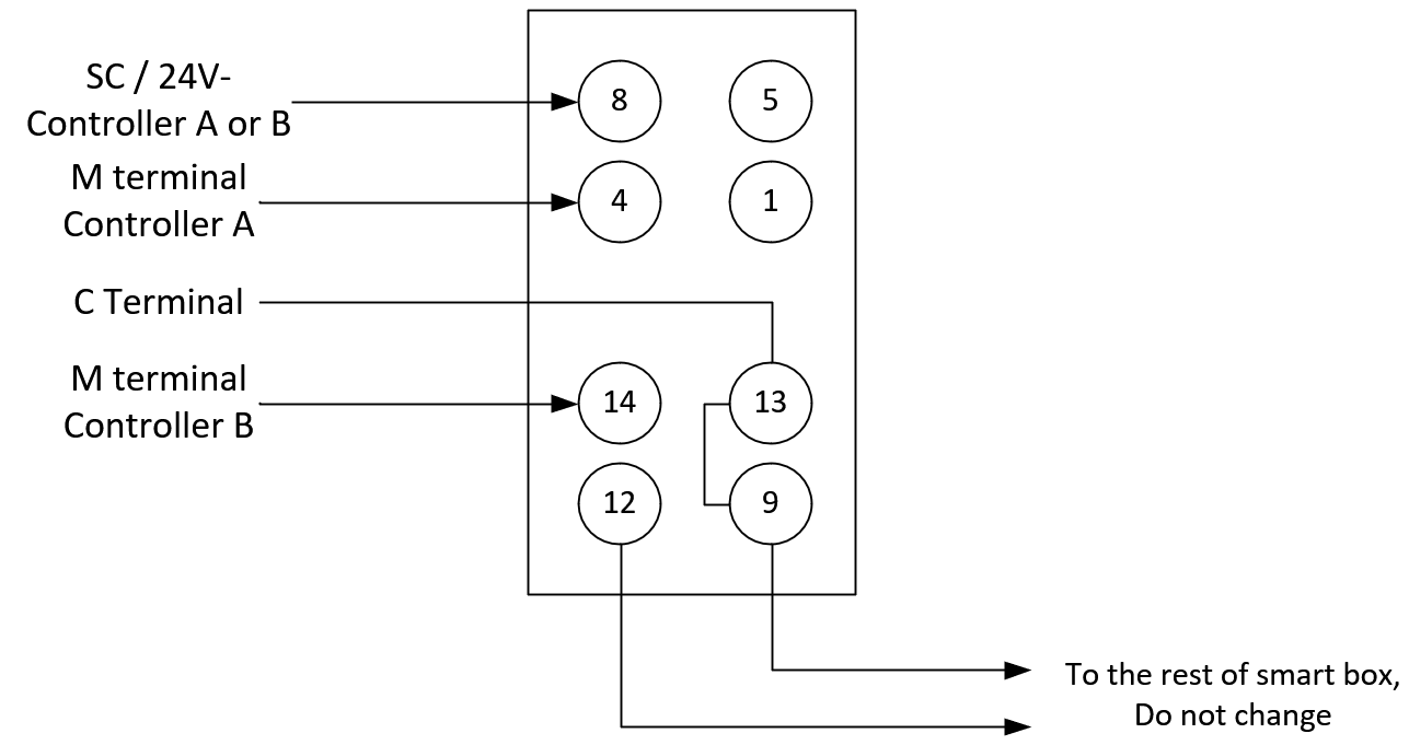
And for clarification, I am disconnecting the jumper wire between 8 and 14, AND the jumper between 5 and 13, correct?
post by Gene on Oct 1, 2019
1
Yes, you are completely removing the (black) jumper between 8 and 14 and moving one leg of the (white) jumper between 13 and 5 to leg 9 (from 5)
post by AngryIrrigationMan on Oct 2, 2019
Update: I pleased to announce that the surgery went well - and more importantly, I think this setup (the last image) WORKED! I manually switched on 10+ zones on both controllers - and I did NOT experience a single master zone fault!! I hope I am not jinxing it as I post this as I will test it with schedules and more manual runs tomorrow. Fingers crossed!!
post by AngryIrrigationMan on Oct 3, 2019
Very Interesting developments on this end - good news and bad news. Good news: I have manually run the zones 10 to 15 times - all WITHOUT zone fault errors! Bad News - strange master fault error on a scheduled items that doesn’t exist.
BEFORE I FORGET: @franz 1. I think @DLane and @Gene deserve another accolade on the support site beyond ‘Power User’ with their MacGyver-like skills! They have been fantastic as I have been fighting this issue for years. I can’t thank them enough for sharing their experience with me in a way that I could act on it! How can we buy someone a drink through this support tool? 2. I do have a FIRMWARE question below that may require your insights / considerations.
To everyone: I did discover a FAULT error with a ‘scheduled’ item - but this is strange and I am not sure this is related to the two controller issue with the Munro box. I woke up to seeing this in my inbox:
\ email-error-schedule-fault.png1138×1208 89.3 KB](https://community.rachio.com/uploads/db1097/original/2X/9/907970c703c1d3c8fb5263faeda07804bf9c0410.png "email-error-schedule-fault.png")
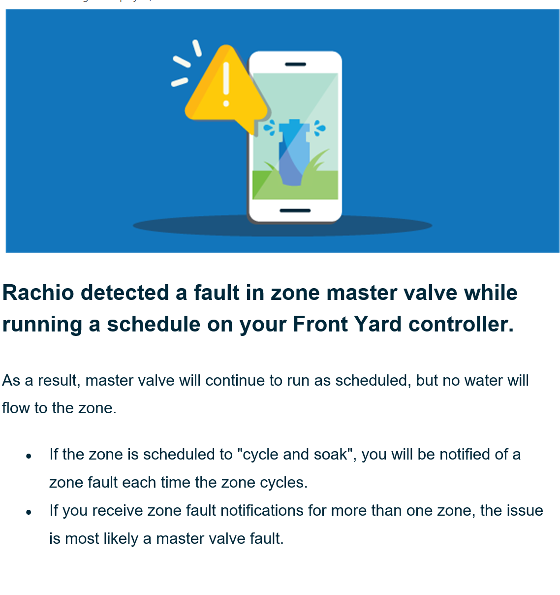
I thought that was strange as I don’t have any schedules - as it references an 11:30 pm schedule. So I checked both controllers - and to prove that I am not going crazy. Here is the Front controller:
Here is the Back controller:
Puzzled, I started looking at comparing both controllers - and noticed that the FIRMWARE on the Front controller (that generated the master fault error) was NOT the same as the back controller. So I updated the FIRMWARE to make sure they are in synch. So I am wondering:
- Could the FIRMWARE have an impact on generating these fault errors? That’s the biggest question I have - and obviously can not answer.
- How do I know if there is a ‘hidden’ schedule in one of the controllers? I used to have many scheduled items in these controllers (alternating so they would not conflict/both be running at the same time) in a Gen 1, then I migrated them to Gen 2 and then Gen 3 (all to try to troubleshoot this). I kept the schedules in place and finally deleted them on the Gen 3 to try to trouble shoot.
Way forward: I plan on 1) adding a new schedule item to both controllers and then delete them - to see if that cleans up the invisible scheduled items 2) Add a couple new schedule items, not using old times, to continue on the great work above by @Gene and @DLane.
post by Gene on Oct 3, 2019
@AngryIrrigationMan Can’t comment on what exactly could have caused the erroneous email, my guess it likely got queued some time ago (have you ever had 11:30PM schedule?) and just got out to you. Wouldn’t worry about it too much, unless it happens again. Does the error show up in the history tab within the app / website?
post by AngryIrrigationMan on Oct 3, 2019
1
Great idea about checking the website as I forgot about using that for admin features in today’s app-centric world! And yes - I did have a schedule at that time as some point.
So on the website, I did not see any other schedules listed either - BUT I did see that it had one of my prior controllers there. So I deleted that just in case that may cause any confusion. I guess I’ll wait to see what happens at 11:30 pm tonight!
To answer your other question - yes, it shows that I have many scheduled items running! Very strange indeed.
post by DLane on Oct 3, 2019
@AngryIrrigationMan - thanks for the update and the compliment.
@Gene and I enjoy the challenges!
post by franz on Oct 3, 2019
franz Co-Founder/CTO @ Rachio
post by AngryIrrigationMan on Oct 4, 2019
Darn - I just recieved another zone master error while manually testing. Looking at the History - I think the controller is running old schedule - while I was manually testing it - even though there are none scheduled / showing on the GUI.
\ conflict.jpg2422×2109 983 KB](https://community.rachio.com/uploads/db1097/original/2X/3/30f109e5bc6b289f1a5a92a14e9f4f0f5d3a62c1.jpeg "conflict.jpg")
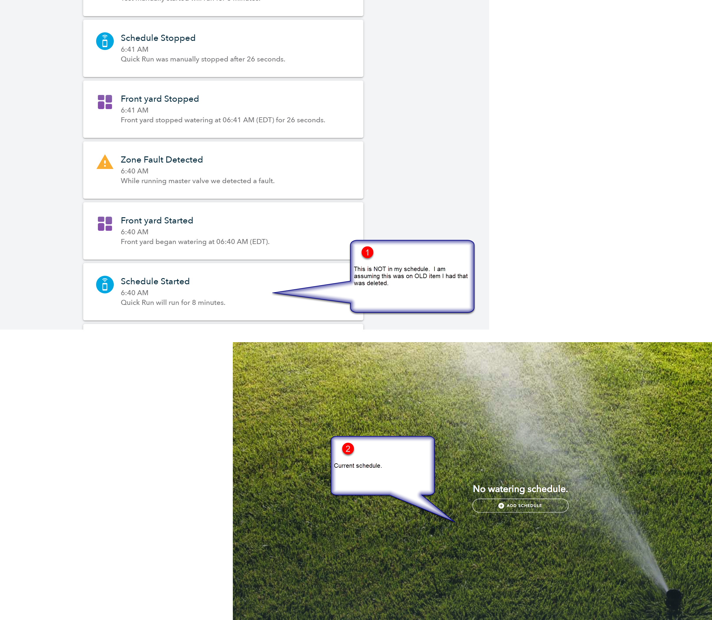
I will research this more - but I may just wipe the controller / set to the initial factory default settings (I assume I can do that) and hope that will delete these hidden schedules.
Note: I think this is a different issue that the relay configuration above. Let me do some more tracking and I’ll keep everyone posted.
post by Gene on Oct 4, 2019
2
“Quick Run” is a type of schedule that Rachio creates on the fly whenever you ask it to manually run anything, it exists only for the duration of the run and would not show up on the schedule list as it is not an actual (recurring) schedule.
What controller did this happen to (is it A or B on the diagram)? What was the status of the second controller at this time?
One thing worth trying is to swap which terminals of the relay (within the smart-box) the M signals from the controllers go to. Connect which ever controller was connected to terminal 4 to terminal 14 and visa versa. Leave everything else as is.
Basically I may have been wrong about allowing controller A or B to supply 24V- signal, Iit may need to be the same controller as that which connected to terminal 4.
\ image.png1287×681 17.8 KB](https://community.rachio.com/uploads/db1097/original/2X/f/f0127763d9fbc05704a9d298217fee4ba8ab0aae.png "image.png")

post by AngryIrrigationMan on Oct 7, 2019
1
Interesting on the ‘Quick Run’ as it’s very confusing because the first word in ‘Schedule’ (in large font/ bond letters) - but I get it now. The other controller has nothing going on - both these have nothing on them as I have tried to make them as simple as I can for this troubleshooting process.
Some stats: I have manually started Quick Run jobs ~10 times and it generated faults only 2 of those times. Unfortunately I don’t see a pattern to it yet.
I will try switching terminal 4 and I will keep you posted! Thank you!
post by AngryIrrigationMan on Oct 12, 2019
So I checked today and that the way wired that way (Terminal 4 connected to the same controller as as the 24V -).
BUT it’s been very strange here: over the last 2 days I had a spike in the amount of Master Valve errors - back to the 3 out of 4 times I get errors. I have done nothing to the system (no wiring adjustment, no schedule adjustments - just random turning on Quick Runs). During that time, I think (not sure) that if I run controller 2 first, then controller 1 within a couple minutes that controller 1 is done/or I force it to stop, controller 1 does not give me a master valve fault error. I am planning on taking the History information from both controllers, merging them into a spreadsheet to see if there is a pattern. Not sure what that will help with.
post by Gene on Oct 13, 2019
Been thinking about your findings @AngryIrrigationMan . @franz, could this error be associated with too much current drawn by the master valve? I do seem to remember that “shorted” zone gives a different error, but can’t seem to find a specific documentation to that fact. We may have tried to “fix” the wrong error, zone being overloaded (too much current) rather than disconnected (no current).
post by franz on Oct 14, 2019
franz Co-Founder/CTO @ Rachio
Interesting, could be. This could be trending above my pay grade.
post by Gene on Oct 15, 2019
@franz any chance of sending it up the chain?
post by dgp on Oct 16, 2019
Firmware person here…
I can’t remember if the reporting is different for over and under current situations but the firmware is looking for both. So potentially this isn’t the controller thinking the zone is over current but actually the zone not drawing enough current and the firmware reporting a fault because it thinks the zone is open.
I’ll try to dig up the actual fault reports from the controller so we can get to the bottom of this.
post by franz on Oct 16, 2019
franz Co-Founder/CTO @ Rachio
AngryIrrigationMan](https://community.rachio.com/t/2-controllers-with-munro-smart-pump-relays-does-it-work-yes-no/20585 "Load parent post")
Can you PM me the email address you use for your Rachio account?
post by AngryIrrigationMan on Oct 21, 2019
Ok - all info has been passed along to the great Rachio machine in the sky via @franz
post by AngryIrrigationMan on Oct 25, 2019
FYI - I generated another Master Value fault this morning on the Front controller. So the technicians can look at that error code.
post by AngryIrrigationMan on Oct 28, 2019
3
@dgp FYSA: I created at least 3 or 4 additional faults on the Front zone for the logs to be reviewed.
post by Gene on Oct 31, 2019
@dgp @franz any chance for an update? Curious as to what the controller is actually seeing.
post by AngryIrrigationMan on Nov 4, 2019
It must be top secret …
28 days later
post by AngryIrrigationMan on Dec 2, 2019
dgp](https://community.rachio.com/t/2-controllers-with-munro-smart-pump-relays-does-it-work-yes-no/20585 "Load parent post")
Any status on this? Smoke signals? SOS? Bat signal? Anything???
Reply
New & Unread Topics
Topic list, column headers with buttons are sortable.
Want to read more? Browse other topics in Sprinklers & Irrigation or view latest topics.
Invalid date
Invalid date